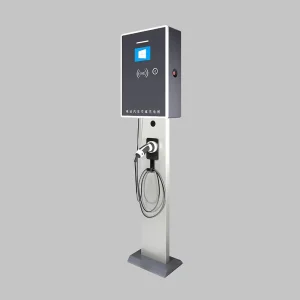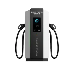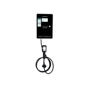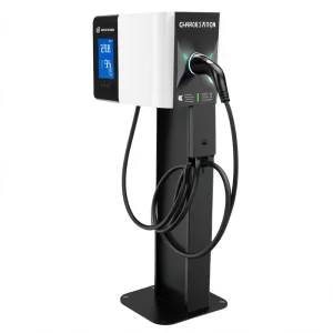
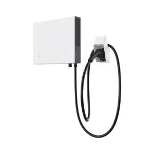
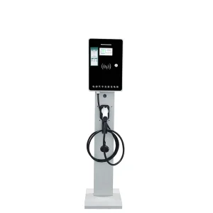
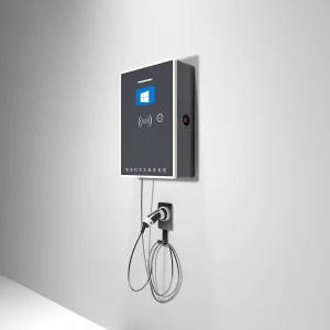
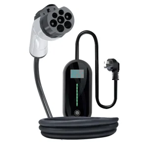
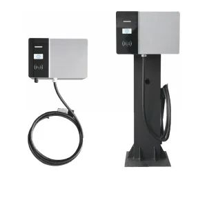
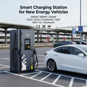
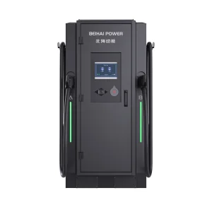
Deploying electric vehicle supply equipment (EVSE) at scale demands a granular understanding of electrical parameters and power constraints. Level 2 charging acts as the foundational baseline for both multi-residential and commercial EV charging infrastructure globally. Unlike low-output Level 1 standard units, Level 2 EVSE utilizes alternating current (AC) grids ranging from 208V to 240V (single phase) up to 380V to 415V (three-phase) systems. This allows for significantly accelerated charging speeds while keeping installation costs highly competitive compared to direct current (DC) fast-charging infrastructure.
From a technical standpoint, the power output of a Level 2 AC system is calculated using the standard electrical power equation:
For a standard single-phase North American commercial deployment utilizing 248V, a 32A configuration yields approximately 7.4 kW of continuous output. In European and Asian industrial configurations, utilizing a three-phase 400V grid, a 32A charger outputs up to 22 kW. Determining these constraints is essential for matching grid capacity with vehicle on-board chargers (OBC), ensuring zero thermal faults and maximizing performance efficiency.
The chart below illustrates the structural power specifications required for continuous Level 2 operations. This ensures that infrastructure developers, electrical contractors, and site planners select appropriate circuit breakers and wire sizes.
| Rated Power | Rated Current | Supply Voltage | Phase Configuration | Min. Breaker Size | Recommended Wire Size (Copper) |
|---|---|---|---|---|---|
| 3.7 kW | 16A | 230V AC | Single-Phase (1P+N+PE) | 20A | 3G 2.5 mm² / 12 AWG |
| 7.4 kW | 32A | 230V AC | Single-Phase (1P+N+PE) | 40A | 3G 6.0 mm² / 10 AWG |
| 11 kW | 16A | 400V AC | Three-Phase (3P+N+PE) | 20A | 5G 2.5 mm² / 12 AWG |
| 22 kW | 32A | 400V AC | Three-Phase (3P+N+PE) | 40A | 5G 6.0 mm² / 8 AWG |
| 19.2 kW | 80A | 240V AC | Single-Phase (1P+N+PE) | 100A | 3G 25 mm² / 3 AWG |
*Note: Wire size estimates must be adjusted based on cable routing length, ambient installation temperatures, and local regulatory codes (e.g., National Electrical Code NFPA 70 in North America).
Residential apartments and condos require dense parking layouts. Utilizing 7.4 kW Level 2 chargers paired with dynamic load management allows buildings to charge dozens of vehicles simultaneously without upgrading utility transformer feeds.
Workplace charging demands standard 8-hour continuous power delivery. Under typical 208V split-phase commercial grid systems, 7.4kW chargers automatically adjust outputs to sustain grid equilibrium while ensuring full batteries by end-of-shift.
Malls, sports arenas, and hospitality centers install high-amperage 22 kW units to cater to short-duration visitors. Accelerated AC outputs offer users up to 100 kilometers of range within a brief 2-hour shopping window.
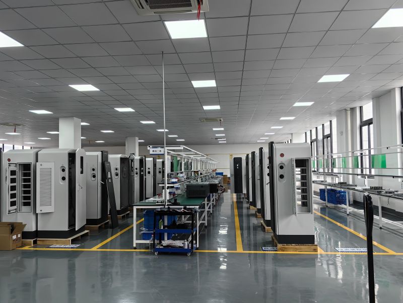
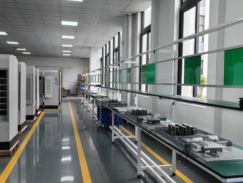
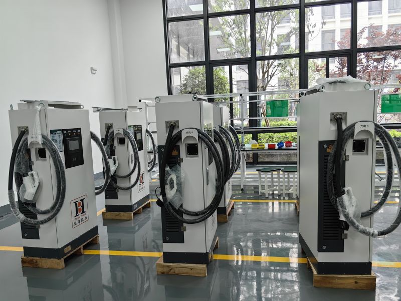
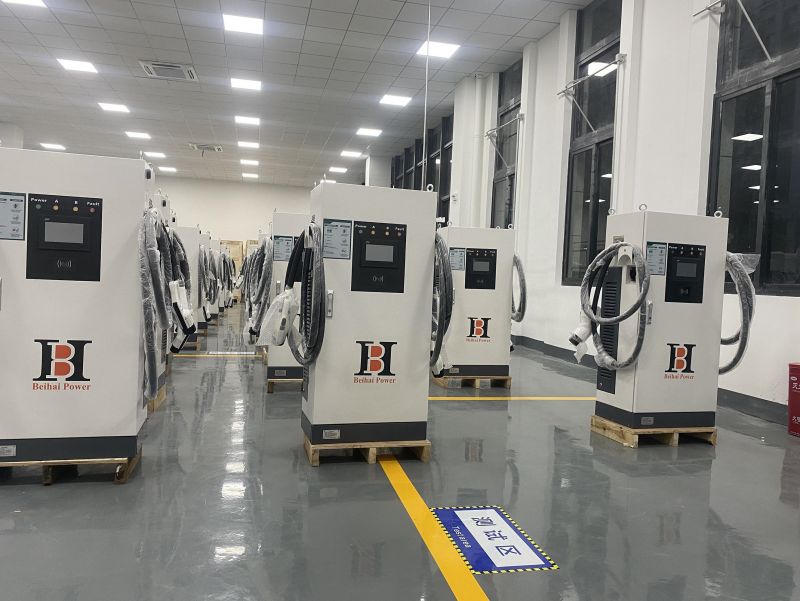
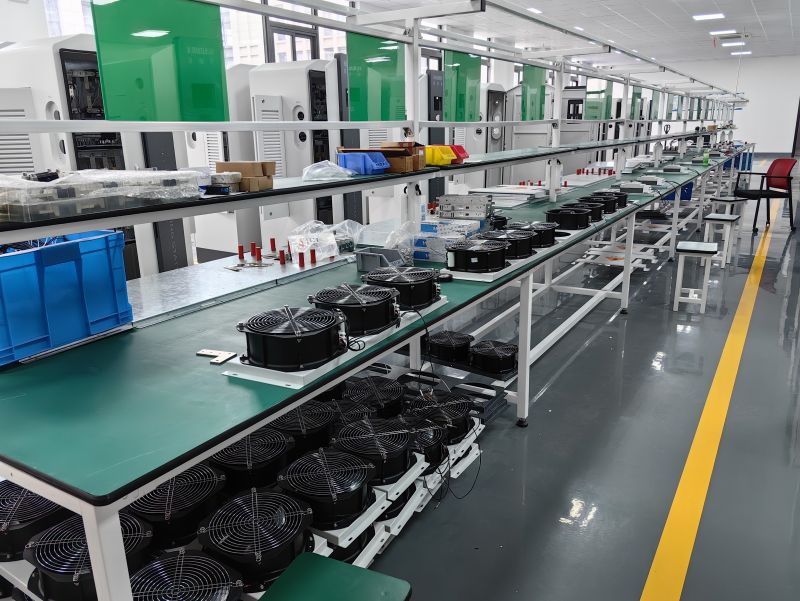
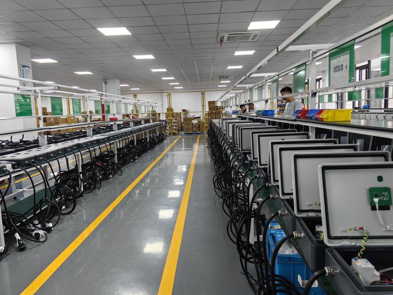
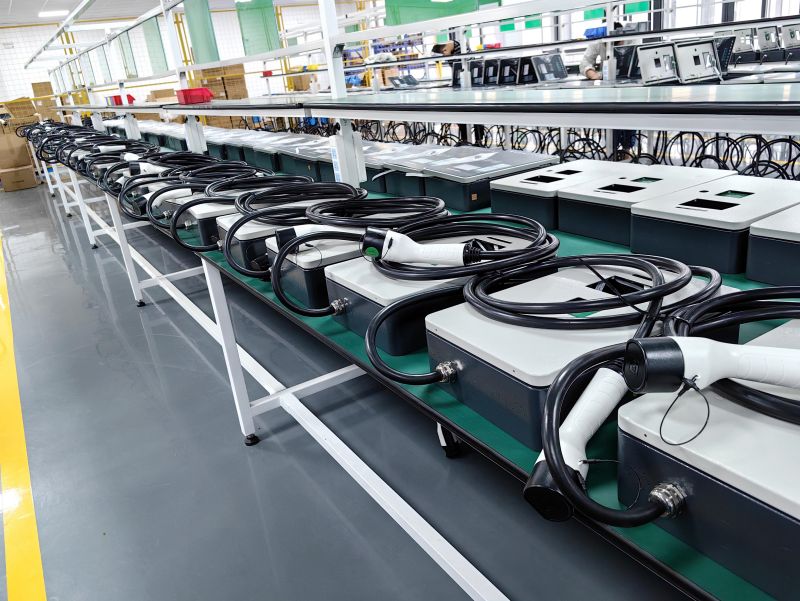
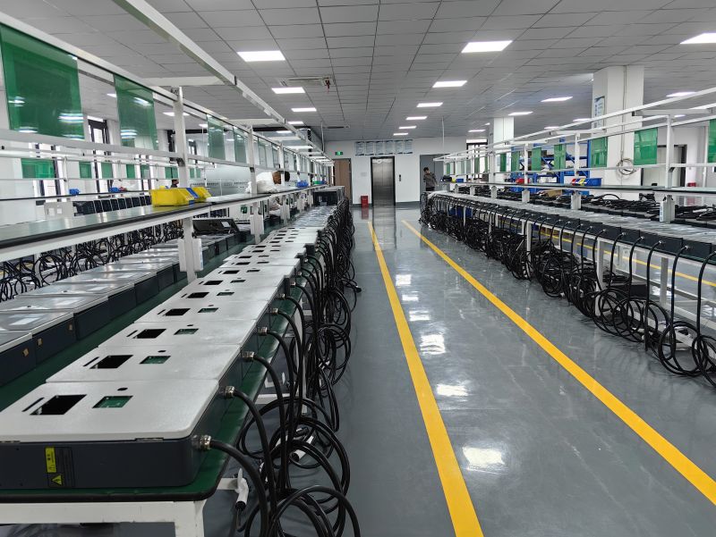
Beihai Power integrates strict international quality control measures at every checkpoint of our EVSE assembly line.

The competitive advantage of China’s EVSE manufacturing lies in its deep supply chain clusters and vertical process integration. At Beihai Power (China Beihai Power Co., Ltd.), we specialize in bridging the gap between high-complexity electric requirements and site installations. From processing premium raw components to delivering fully assembled, custom-configured commercial models, our logistics and operations guarantee robust and cost-effective output.
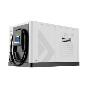
By controlling sheet metal fabrication, PCB electronics layout, and software integration under one roof, we significantly reduce shipping lead times and eliminate system compatibility failures. This dynamic ecosystem allows us to customize hardware architectures—such as delivering specialized 150kW Mobile DC configurations for recovery vehicles in Colombia and the US, or shipping bulk runs of 24 multi-gun systems to Uzbekistan—within compressed schedules.
High-precision laser processing of high-grade steel and composite alloys.
Heavy-duty cabinet creation featuring anti-corrosive powder finishes.
Structural framework integration and optimized internal electrical wiring layout.
SMT layout production for main controllers, smart metering, and communication components.
Strict verification of mechanical seals, isolation resistance, and ingress protection (IP65).
Simulated load cycles, dynamic heat testing, and software validation (OCPP protocols).
Beihai Power is not merely an equipment manufacturer. We deliver comprehensive solutions that power critical public fleets, shipping channels, and commercial infrastructure globally.
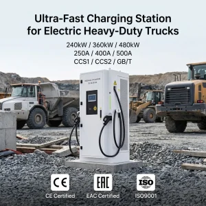
When a logistics enterprise in Colombia needed a flexible roadside recovery charge solution, off-the-shelf Level 2 AC installations were insufficient. Beihai Power engineers customized a 150kW Mobile DC fast charger module integrated into mobile recovery vans, designed to interface seamlessly with standard vehicle battery management systems (BMS). Similarly, for heavy-duty transit networks, our 360kW liquid-cooled charging points serve high-volume fleets, demonstrating our technical capability across high-current and extreme thermal conditions.
Whether installing chargers on a 60Hz split-phase grid in North America or a 50Hz three-phase distribution grid in Central Asia or Europe, Beihai Power systems adjust dynamically. Built-in smart power sharing ensures that when grid capacities drop, charging piles communicate intelligently via OCPP 1.6J/2.0.1 to balance output currents, safeguarding both grid assets and vehicle electronics.
As EV integration deepens, future-proofing infrastructure requires advanced software protocols and hardware layers. The transition toward Vehicle-to-Grid (V2G) and Vehicle-to-Home (V2H) topologies will transform Level 2 AC installations from simple energy sinks into dynamic grid nodes. This is guided by the ISO 15118 protocol, which standardizes bi-directional power exchange and automatic "Plug & Charge" verification.
Beihai Power is at the forefront of this technical shift, developing native hardware modules supporting bi-directional sub-systems. This allows commercial site operators to capture stored battery energy from connected fleet vehicles during periods of high peak demand, returning energy to the grid or offset billing charges.
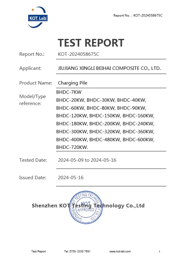
International expansion requires strict adherence to regulatory standards. Beihai Power products undergo safety assessments to meet international criteria:
Our factory meets rigorous ISO 9001, ISO 14001, and ISO 45001 management criteria.




Here are answers to key technical questions from fleet operators, engineers, and supply leads regarding Level 2 charging infrastructure.
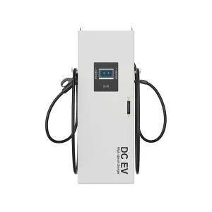
Level 2 chargers operate using alternating current (AC) and rely on the vehicle’s internal On-Board Charger (OBC) to convert power to DC for battery storage, using standard 208V–240V (single phase) or 380V–415V (three-phase) systems. Level 3 DC fast chargers bypass the OBC, converting power from AC to DC within the charging station cabinet before delivery to the vehicle. This enables direct delivery up to 1000V and requires high-capacity industrial grid infrastructure.
National Electrical Codes (such as the NEC in North America) classify EV charging as a continuous load (running for 3 hours or more). Safety regulations dictate that continuous loads must not exceed 80% of the circuit breaker's rated capacity. Therefore, a 32A continuous load requires a breaker size calculation of: 32A ÷ 0.80 = 40A.
Many premium Level 2 three-phase chargers (e.g., 22 kW units built to European standards) are backward-compatible with single-phase lines. However, the charging output drops from 22 kW down to 7.4 kW because the unit utilizes only one of the three current paths. Hardware configurations must be reviewed to ensure correct neutral connections.
Dynamic load balancing systems continuously monitor total current utilization at the facility main distribution box. When overall usage spikes, a central control module communicates via OCPP commands to adjust the charging rate (amperage) of each active port, ensuring the system remains within safe limits.
Certified chargers must include short-circuit mitigation, over-temperature thermal shutdowns, ground-fault leakage monitoring (Type A AC + DC 6mA monitoring), lightning surge protection, and flame-retardant enclosures.